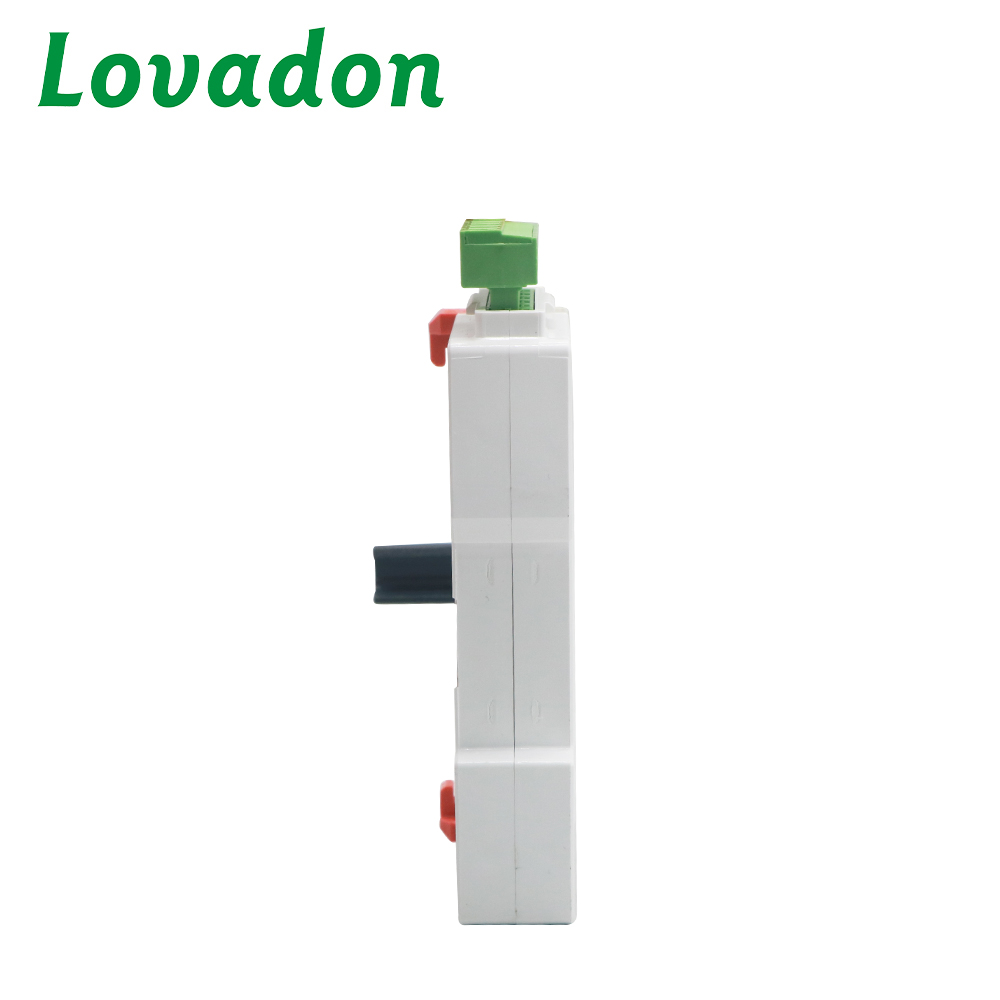
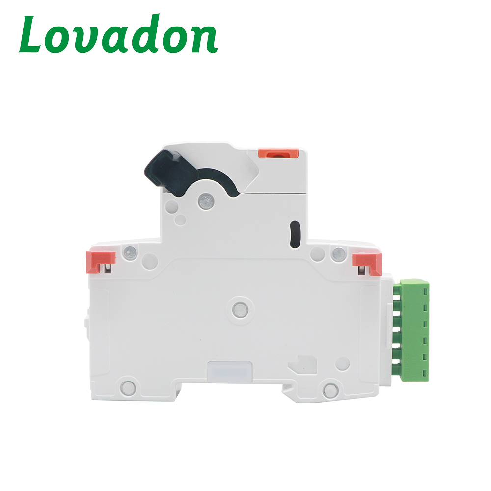
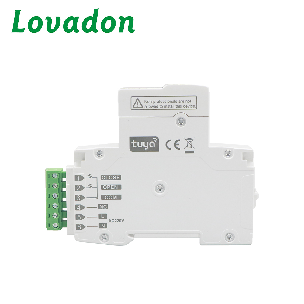
General
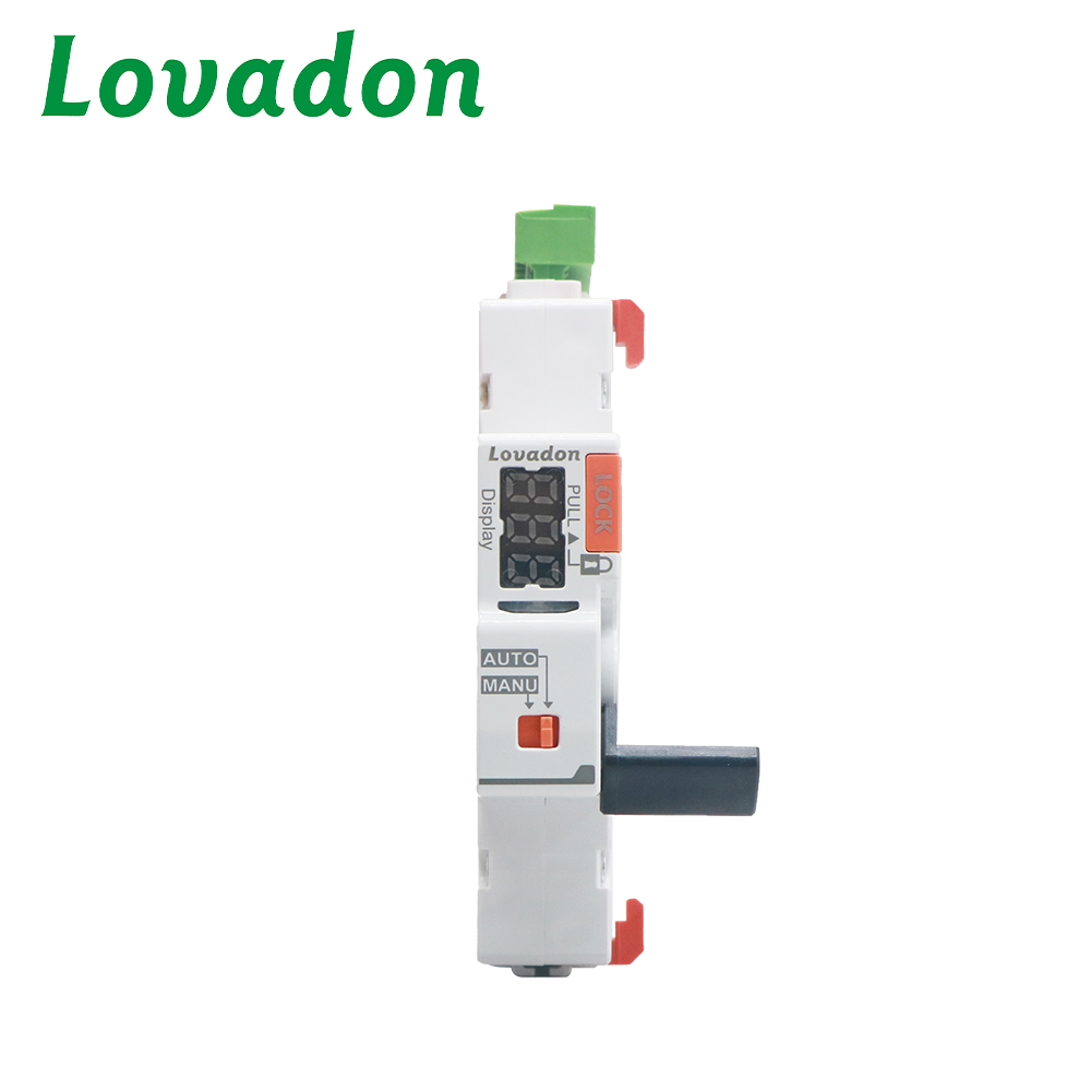
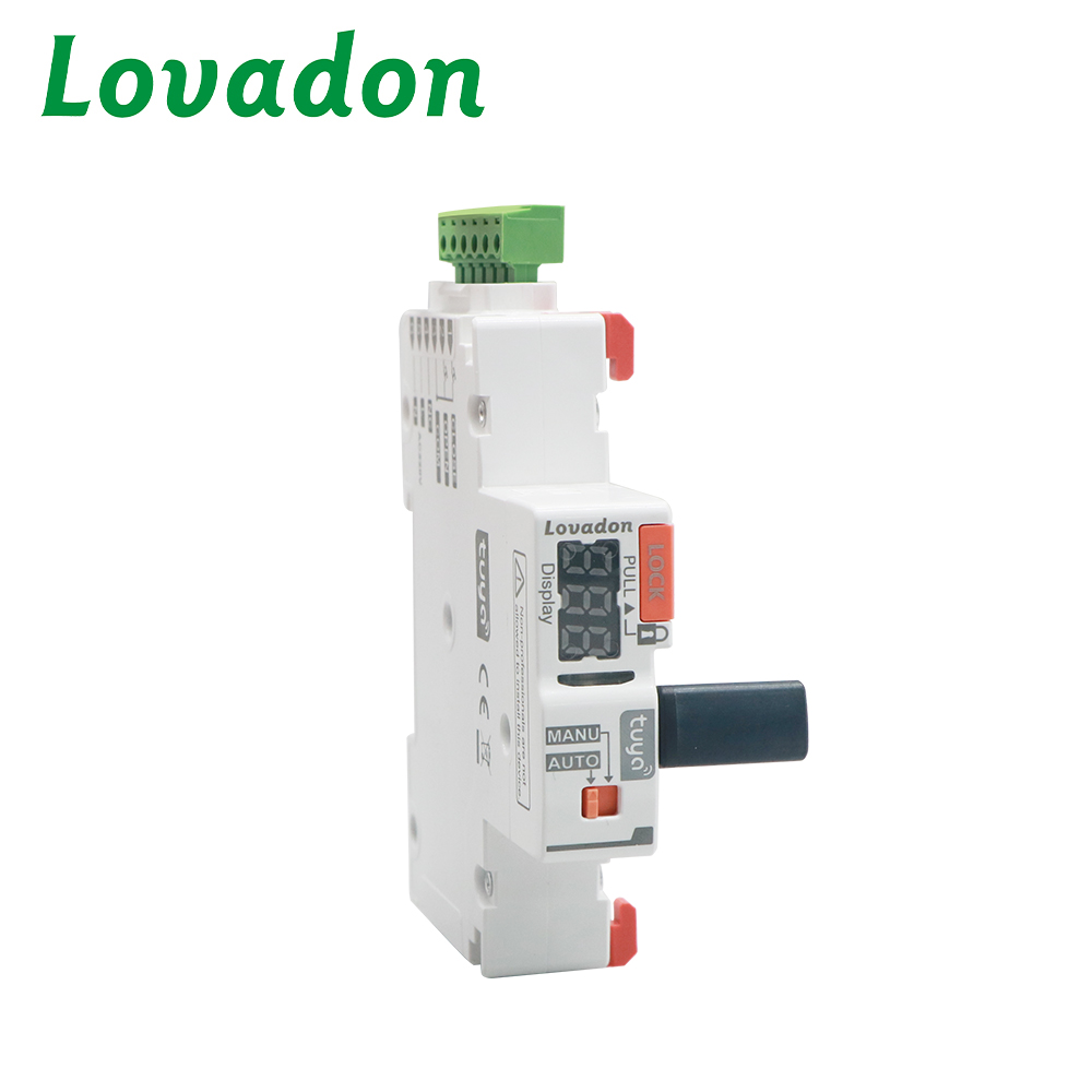
It can be remotely controlled by Smart Life App for automatic closing and opening , have parameterized and configurable functions which can be automatically judged by MCU ,realizing the function of opening the circuit breaker when power outage and automatically closing when power on. Currently widely used in photovoltaic grid-connected AC distribution boxes , as well as the following occasions, including places that are difficult for personnel to access , places where maintenance personnel cannot be in place in time, unattended occasions, and places with high requirements for power supply continuity.
Please note
1. Equipment installation, maintenance and replacement must be completed by qualified electricians.
2. Repairs to the equipment are prohibited.
3. All applicable local, regional and national regulations must be followed when installing, using,maintaining
and replacing equipment.
4. If the device is found to be damaged when unpacking, please do not install it.
5. The company is not responsible for any adverse consequences caused by failure to comply with the in-
structions of this document and the documents mentioned in the article.
6. Relevant maintenance regulations must be strictly followed throughout the entire life cycle of the equip-
ment.
7. There may be a risk of electric shock, explosion or arc burns.
8. Be sure to cut off all power supplies before maintaining the equipment.
9. Use an electroscope with an appropriate voltage rating to confirm that all conductors are uncharged.
10. Failure to follow the above instructions will result in personal injury or death.
Technical Parameters
| Parameter | Specification |
| Standard | EN 50155, GB/T 24338.4-2018, EN 45545-2, IEC 61373 |
| Operating Voltage | 230V AC (70%~125%) |
| Control signal | MODBUS-RS485 Wet node 230V high level/pulse signal (optional) |
| Over&Under voltage function | 160-275V ±5V (optional) |
| Timing function | Available (optional) |
| Digital display | 3-digit voltage, switching times, fault status |
| Effective control signal duration | >400ms |
| Closing action time | < 1s |
| Opening action time | < 0.5s |
| Control circuit cable length | ≤1500m |
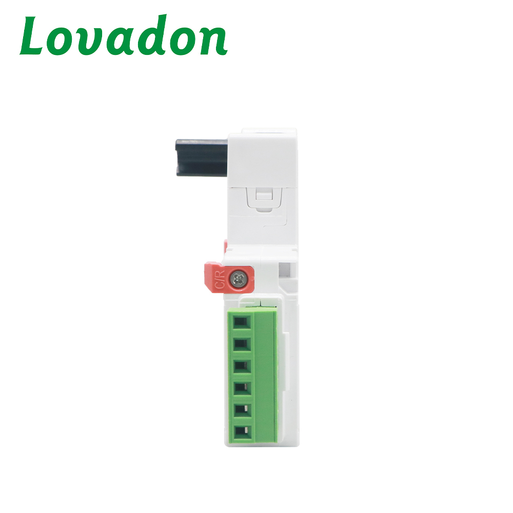
| Current-carrying capacity of auxiliary contacts (terminals 8-9-10) | 1CO, minimum operating current 3mA (24VDC) (resistive) (optional) |
| Current-carrying capacity of signaling contacts (terminals 5-6-7) | Maximum operating current 2A (30V DC), 0.5A (125V AC) (optional |
| Power consumption | ≤ 1.5VA (static); ≤25VA (dynamic)400V |
| Rated insulation voltage | 400V |
Rated Impulse Withstand Voltage Uimp (between S2C-RM DC and MCB | 4kV (4.9kV at sea level) |
| Self-locking proteaction | Within 10s of 3CO / 20s of 4CO / 30s of 6CO, the product will self�lock and recover automatically after 40s. |
| Electrical life | 10000 times, 3 times/minute |
| Power and control signal terminal wiring capacity | 28-12AWG 2.5mm² |
| Auxiliary signal terminal wiring capacity | 28-12AWG 2.5mm² |
| DIN rail mounting | DIN rail EN 60715 (35 mm) |
| Mounting position | Mounting on DIN rail Any position |
| Indicator Light | Green, Normal status Red, MCB overcurrent fault |
| Auto/Manual switching | Auto Remote control of opening&closing available Manual Remote control of opening&closing disabled |
| Mechanical life | 10000 |
| Protection class | Ip20 |
| Hazard class according to EN 45545-2 | EN 45545-2 R26 /Hl3 |
| Shock and vibration resistance According to IEC 61373 | cat egory 1 - class A/B - body mounted |
| Resistance to heat and humidityIEC/EN 60068-2-30 | 28 cycles (55°C/90-96 % , 25°C/95-100 %) |
| Ambient Temperature | -25 ~ +70°C |
| Storage Temperature | -40 ~ +70°C |
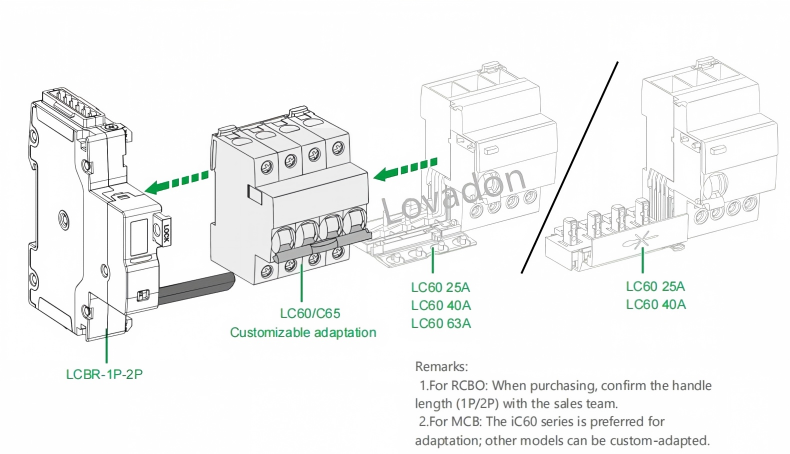
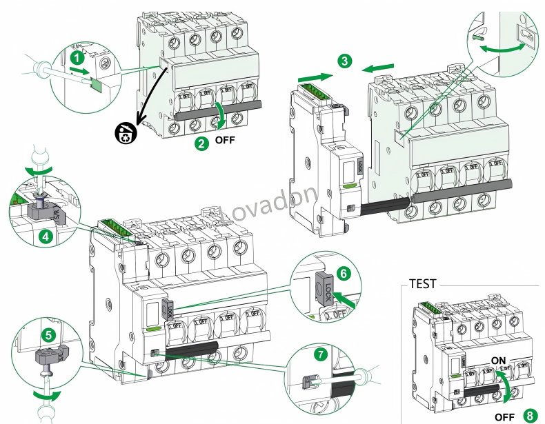
Installation method

 Yueqing Lovadon Electric Co., Ltd.